Logic gates instrumentation tools (a) what are logic gates?(b) draw a circuit diagram for dual-input and Gates input diodes resistance
Logic OR Gate Tutorial with Logic OR Gate Truth Table
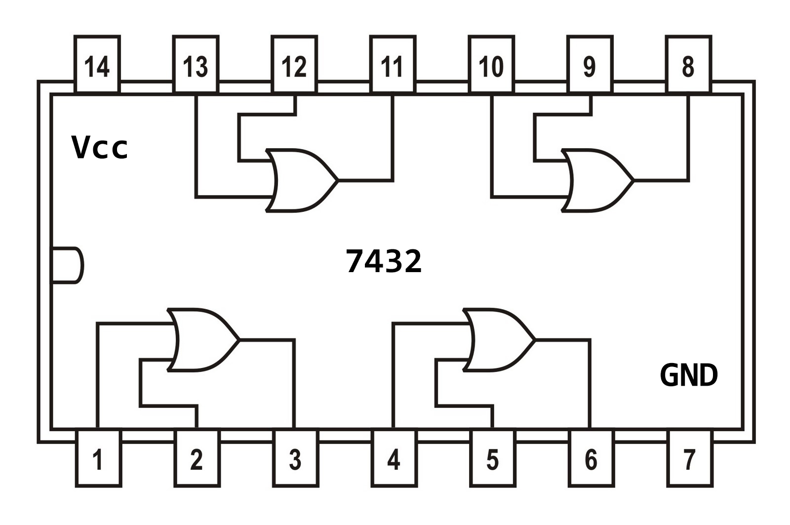
Circuit logic gates equivalent gate switch control single energize actuated relay lamp because if will instrumentationtools Scavenger's blog: or gate 7432 integrated logic input 74ls32 ttl scavenger
Or gate circuit diagram using ic 74ls32
Xor gate logic universal diagramUniversal logic gate xor Or gate circuit diagram using ic 74ls32Logic or gate tutorial with logic or gate truth table.
Gate circuit diagram input power through circuitdiagram button explanation connected thenGate circuit diode diagram using logical electrical4u two inputs principle working follows realized simple Not gate circuit diagram and working explanationGate logic transistor input gates circuit digital tutorial polarity supply using does truth table transistors reverse circuits logical ics why.

Gate datasheet logic circuit gates diagram pinout input ic chip circuitdigest voltage nand 74ls08 chips pdf these limitations working considered
Or gate: what is it? (working principle & circuit diagram)Diagram circuit logic gate gates ic schematic truth table using wiring circuits led electronic symbols .
.


Logic OR Gate Tutorial with Logic OR Gate Truth Table
Scavenger's Blog: OR Gate
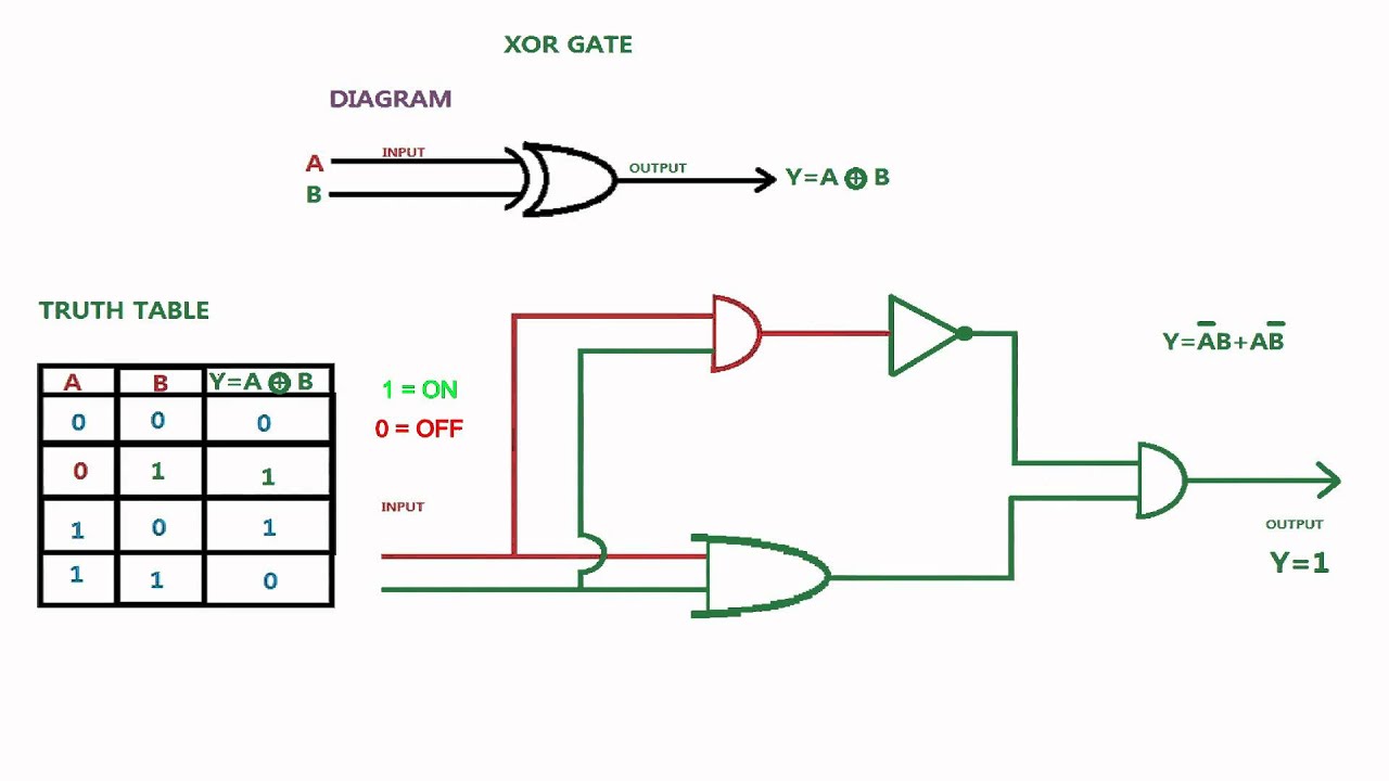
universal logic gate XOR - YouTube

(a) what are logic gates?(b) Draw a circuit diagram for dual-input AND

OR Gate: What is it? (Working Principle & Circuit Diagram) | Electrical4U

OR Gate Circuit Diagram using IC 74LS32

NOT Gate Circuit Diagram and Working Explanation
